Modulo 3 counter design and circuit Counter plc circuit 17. up-down counter types and instructions – msblab
f-alpha.net: Experiment 4 - Mod-6 Counter
Counter mod diagram circuit flip mod6 flops experiment gate alpha reset electronics Counter counters modulus decade truncated Counter output diagram
Mod counters – all about electronics
Counters modulus truncatedMod counters – all about electronics Digital design: counter and dividerCounter timing modulo counters zähler.
Counter mod circuit experiment alpha electronicsMod counters – all about electronics F-alpha.net: experiment 4F-alpha.net: experiment 4.

Counter circuit divide modulo mod flip using flops digital counts three
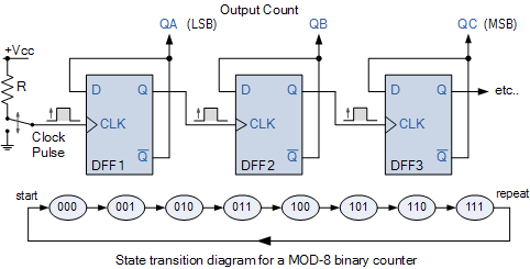
Counter state diagram mod digital divider transition figureThe mod 6 down counter while output is 5. .
.


MOD Counters – ALL ABOUT ELECTRONICS

f-alpha.net: Experiment 4 - Mod-6 Counter

Modulo 3 Counter Design and Circuit

The Mod 6 Down counter while output is 5. | Download Scientific Diagram

17. Up-Down Counter Types and Instructions – MSBLAB

MOD Counters – ALL ABOUT ELECTRONICS

f-alpha.net: Experiment 4 - Mod-6 Counter